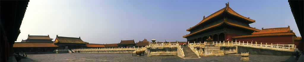
Imaging geometry for panoramas
Pinhole imaging
Figure 1 shows the way that rays of light from an object form an image in a camera.The bigger the lens is, leaving everything else the same, the lower the f number, that is the brighter the image on the film or digital sensor. Most of lens design is about creating a combination of large lens and high image resolution, i.e. accurate focussing of rays on the image plane (the film or sensor). For the discussion of panoramic images we can mostly assume that the lens designer did a good job and only take into account the light ray that goes through the centre of the lens. This is like turning the camera into a pinhole camera. Nothing changes position on the image plane. In practice very little light would get to the image plane, and the image would not be very sharp, but it is a good enough approximation for what follows.

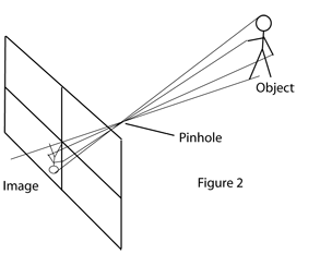
Most cameras produce an image on a flat surface, either the film or semiconductor digital imager. Figure 2. By changing the angle of the camera we get a new image of the scene and it would be nice to combine these two images to get an image with wider field of view, that is a panorama.
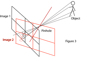
From Figure 3 it can be seen that the two images cannot be accurately combined simply. The two image planes are flat. Where they are imaging the same point the distance from lens (pinhole) to image is different in each image, so that the images have a different scale and do not match. To see this imagine a very wide field pinhole camera. The image magnification, that is ratio of object to image size will be different at the middle and edge of the image. To put it more technically a change in input ray angle produces a bigger change in image position the further one is from the optical axis.
Cylindrical imaging
Patching together images taken with a normal camera is therefore doomed to give an inaccurate result. If the image planes in Figure 3 were instead parts of a cylinder centred at the pinhole the images could be combined because each image plane is part of the same cylinder with the centre of the cylinder at the pinhole position.See Figure 4. There are two basic ways to achieve this. A specialised camera can be made that rotates about the centre of the lens and only exposes a small vertical strip of film at a time. The effect of this is that the image plane is a cylinder. It also has the advantage that the camera can rotate through a full rotation and produce a very wide panorama. There are also digital versions of this system that replace the film with a line of optical sensors to produce the same effect. The drawback of this system is, of course, that you need a special expensive camera.

The second way to solve the problem is to process the flat images from a normal camera so that they are the same as would have been produced if the image plane was a cylinder. Warping the images in this way should then allow and accurate patching together of the different images. This is simple geometry and sounds straightforward. Unfortunately there are quite a few practical difficulties.
- Each image must be from a rotation about the pinhole or effective centre of the lens.
- Each image must use the same focal length lens.
- Each image must not be rotated about the optical axis.
- Each image must have the geometry of a simple pinhole camera. Cameras with pincushion or barrel distortion do not.
- Each image should have the same exposure.
- Nothing in the object should change between the taking of images.
It is unlikely that all of these conditions are met. Special camera brackets have been produced to allow a camera to be rotated about its effective lens centre, which removes parallax between views. Parallax is impossible to remove entirely by software because there may be places on the final cylinder that have not been imaged in any view, and the software cannot produce these. Not changing focal lengths between shots is easy. Not having any rotation of the camera about its optic axis requires careful setting up of the camera mounting. Pinhole and barrel distortion is caused by the image magnification changing between the centre and edges of the image. Panoramas require the use of a good lens. Even this may leave a problem. The exact optical axis of a lens is not necessarily exactly down the physical centre of the lens. Keeping constant exposure between shots in the responsibility of the photographer. Making sure nothing moves between shots is sometimes impossible. Taking a photograph including the sea for example. Rotating cameras have the advantage here because the artefacts produced in the image will be very subtle and probably not noticeable, where separate shots will show obvious joins, unless clever algorithms for moving between input images is used.
The net result of this is that software for combining multiple shots into a seamless panorama is extremely difficult. I am always amazed at quite how good some modern programs are at performing this task. I routinely take handheld panoramas which violate several of the rules for good panoramas, but which result in perfectly acceptable images. The above pair of images shows the same image before and after the image warping stage. This panorama was taken hand held. The warping is asymmetric and also involves a rotation. The software has been working hard to allow a match.
Spherical imaging
Cylindrical imaging as explained above is used to increase the horizontal field of view of view. The reason a cylinder is chosen as the image geometry is so that verticals in the image stay vertical and the azimuthal angle (i.e. rotation about the vertical axis) has no effect on the image geometry. This is not the only possibility. Especially with software techniques it is possible to choose any three dimensional surface to be the imaging surface. ( there are of course limits to this, for example folded sheets). One could choose to project the image on a flat surface for all panoramas less than 180 degrees. This gives a view where the edges are highly distorted, but all straight lines on the object produce straight lines on the image. A more useful one is to change the vertical scale on a cylindrical panorama so that vertical magnification is constant. As with the flat image, the further up or down the cylinder the higher the image magnification (ratio of input angle to distance on image). For a very tall cylinder this can give stretched looking results. Changing the vertical scale with vertical position removes this problem. Its a bit like the map projection of the globe where the vertical scales near the poles are made very small so that the countries areas are accurately represented, but not their shapes.
For very tall cylinders it’s probably not a good idea to use a cylinder at all but use a sphere instead. A spherical projection gives a constant image scale for any point on the sphere. It allows a complete rotation of 360 degrees in both horizontal and vertical directions. This is probably best demonstrated by virtual reality viewing systems like QuicktimeVR that allow the viewer to look in any direction.
The problem with spherical panoramas is printing them. It is easy to print a cylindrical panorama on flat paper by un-rolling the cylinder. This does not work with a spherical projection. There is maybe one exception to this. If you can print the panorama big enough that you can get inside the sphere to view it, the paper curvature is probably small enough to allow multiple separate flat images to be fixed to the inside of the sphere.